Sheet metal design basic fundamentals make manufacturing a sure thing instead of crossing your fingers that everything will turn out ok.
Fundamentals of sheet metal design.
In the ideal.
Sheet metal design is key to the production of quality products.
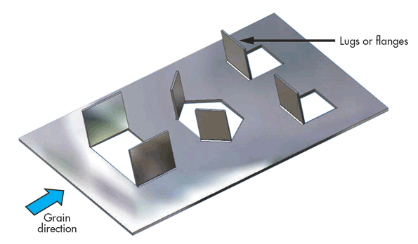
The minimum hole diameter should be equal to or more than the sheet thickness.
There are two images below that show the correct bend radius for a 1 mm thick sheet top and the correct bend orientation for two bends in the same plane bottom.
For manufacturers to come up with desirable quality compliant metal tools they ought to follow specific guidelines.
Many engineers developing 3d models for sheet metal products are unaware of the fabrication tools used to form the part or product and instead design models for an ideal world.
Few thumb rules or sheet metal design fundamentals.
Let s take a look at some examples.
Bends in sheet metal are manufactured using sheet metal brakes.
Sheet metal can be cut bent and stretched into an amazing array of shapes.
Learn more about protocase what we make who we work with our simple design processes and advanced design tools and our 2 3 day manufacturing process.
To meet unique sheet metal design challenges like manufacturability solid edge streamlines the entire sheet metal product development process from cad design through flat pattern and drawing development.
Our customers are experienced sheet metal designers as well as engineers scientists and technologists who build electronics.
When designing parts for laser cutting one should not make holes smaller than the thickness of the material.
Sheet metal parts with a minimum of 0 9mm to 20mm in thickness can be manufactured.
We would like to show you a description here but the site won t allow us.
Design for manufacturability is now a common concept in many industries including the sheet metal design sector.
Unfortunately some creators of sheet metal enclosures and assemblies do not design with the.
Whether you are fabricating military equipment or automobile parts it s essential to follow the stipulated guidelines.