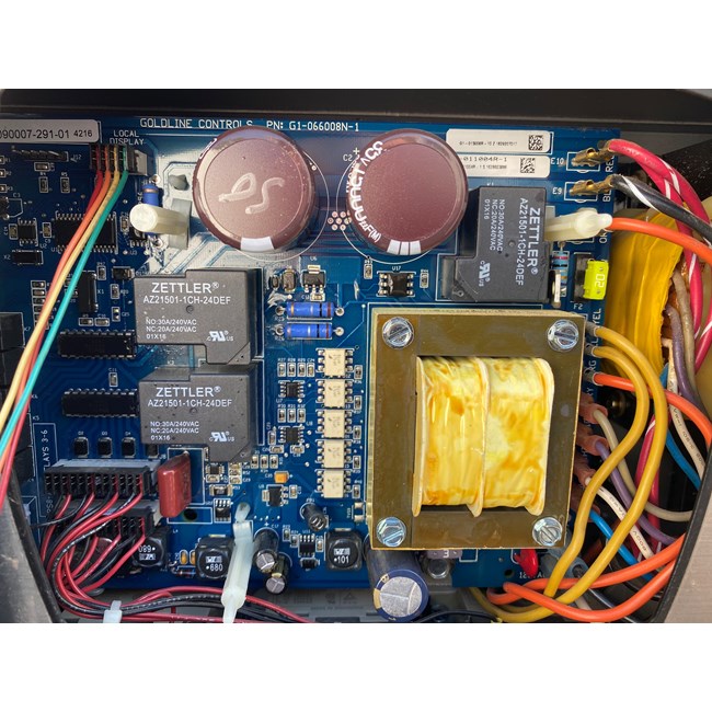
Plug both wire to the fuse directly.
Goldline aqualogic no cell power 2.
Please add liquid chlorine to the pool until the issue has been resolved.
No cell power cell power error low volts stop.
Turn off the main braker unplug the yellow and orange cable above the yellow fuse top right.
Same with the serial numbers on your cells and control boxes after the 5a 5e 5l 3l and 3e.
Unplug the yellow fuse from its socket.
908 355 7995 or contact a pool professional.
The first 2 digits are the year of manufacture the next two the month.
G flow monitor flow switch connector h p transformer input 120vac x 2.
No low voltage detected when the cell power was turned on.
This must be resolved by a certified technician.
In diagnostic mode it shows 0v 0a in both positive and negative polarity so something is definitely wrong.
Goldline controls warrantied these flow switches if they failed in the field and were of the specified lot.
Please contact tech service.
If no voltage is measured continue to step 1b.
Turn on the main braker and your goldline.
I called goldline and they said it is probably the main board.
My display is saying chlorinator off no cell power and check system no cell power 2.
Main pcb layout a i remote dsp comm rs485 10vdc b temp sensor terminal block 5vdc c heater 1 2 terminal block dry contacts d valves 1 4 4amp fuse 24vac e cell plug for chlorination f high voltage relays top filter lights aux1 aux2.
Try starting the filter pump.
No cell power 1 or no cell power 2 no cell power 1 no cell power 2 go to step 1a page 4.
I tried cycling the system at the breaker level on the panel thinking there might be a glitch as well as re seating the cell connector that plugs into the panel.
If i re boot it will display correctly for about a minute and then you can feel the cylenoid looking thing clicking and then it will display as mentioned above.
Verify that 20 24 volts ac is present between the two yellow wires.
If the voltage is ok go to step 1c.